Phase (Frequency) Detector
To mimic the PLL architecture for the CDR, a phase/frequency detector is needed, in order to compare the NCO output clock frequency to the data rate.
To detect a frequency difference, the transition of the data signal shall be compared with the transition of two clocks of equal frequency that have a constant phase difference.
Denoting with \(f_d\) the data frequency and with \(f_{VCO}\) the clock frequency, we have that:
\(f_d = (\phi_d(t_1) - \phi_d(t_0)) / (t_1 - t_0)\)
\(f_{VCO} = (\phi_{VCO}(t_1) - \phi_{VCO}(t_0)) / (t_1 - t_0)\)
The frequency difference is then given by:
\(f_d - f_{VCO} = [(\phi_d(t_1) - \phi_{VCO}(t_1)) - (\phi_d(t_0) - \phi_{VCO}(t_0))] / (t_1 - t_0)\)
Practical implementation
If the data phase is shifting with respect to the clock edges, than the clock quadrant that detects the data transition will increase or decrease, accordingly to the phase shifting direction.
In the implemented design, the frequency detection capability relies on the use of two clock signals, with 50% duty cycle and orthoghonal with each-other. These two signals allows the division of a clock period into four quadrants (see Fig. 3).
To identify the quadrant of the data edges, informations by two Alexander-type phase detectors (Fig. 4) are registered and processed. Further processing is needed to determine whether the data edges are drifting up or down in the clock quandrants (due to higher or lower clock frequency) to consistenly adjust the NCO frequency. These frequency change requests to the NCO are constantly monitored in order to control CDR locked flag.
Informations on the phase and frequency detection techniques whose this design is based from, can be found here [2].
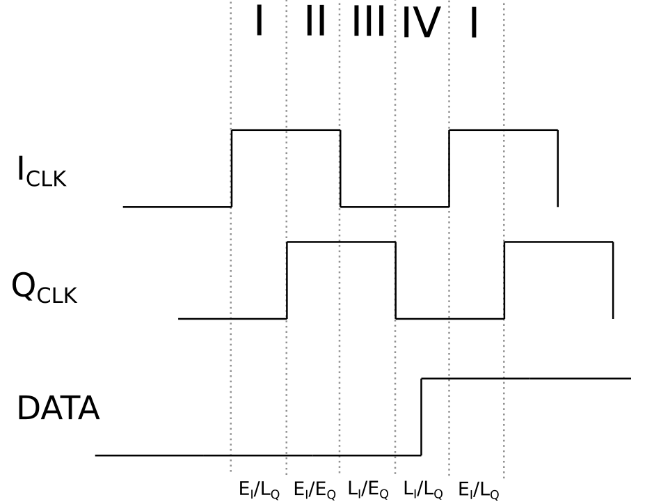
Fig. 3 The division of the clock period in four equal qudrants (indicated by the Roman numerals). \(I_{CLK}\) stands for In-phase Clock, which is the reference, \(Q_{CLK}\) stands for Quadrature Clock, which idetifies the \(+ \pi / 2\) (or \(- \pi /2\)) phase difference clock. To idetify a quandrant, an Early (E) and Late (L) notation (Clk vs Data) is used. If a data transition is first located in quadrant III and then in quadrant II, the data phase is shifting to the left, which equals that the data transitions are based on a clock faster than the NCO clock.
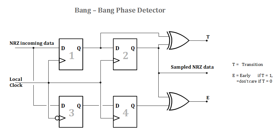
Fig. 4 The bang-bang PD compares the negative edge of the clock with the data transition, and the present data bit with the previous data bit. Using 4 flip flops the resulting info is contemporarily available for one entire clock period. The output T is active when a data transition is detected, the output E is active when the clock has been found early.
| [2] | https://en.wikibooks.org/wiki/Clock_and_Data_Recovery |